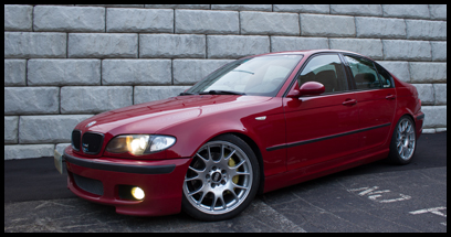
OEM TPMS Retrofit- The full package doityourself
Ok, this DIY retrofit writeup is for the full TPMS package, from the coding to the reset button, to the wiring into the DSC module. Each part of this setup will get its own set of steps. First, a brief description. The OEM TPMS setup does not involve sensors in each wheel, making it fairly easy to retrofit. Also, changing wheels/tires doesn't affect the system at all. The system relies on wheel speed and compares the revolutions of each wheel with each other to determine if one wheel has an incorrect tire pressure. More or less revolutions will occur based on higher/lower tire pressures. The system isn't the most high tech, but it does work, and I can confirm, fairly well. 
So, lets get started!
Part 1: The Coding
Using coding software, you will need to access a couple of modules and make a few changes. There are 4 lines of code needed in the KMB module to get the TPMS system functional. The beauty of this mod is that technically, once the coding is done, the system is functional and you can stop there! The wiring and reset button are only needed for resetting the light/system. But, you can still use the system to monitor your tire pressures. If the light goes off, you'll just need to visit a dealer that can reset the light for you. But I digress... Coding the KMB module, you'll need to find each of these line items. The default setting is in parentheses, you'll need to change them to the other setting.
Description~String~Options (Default)
1. Tire Pressure Control System (RDKS)~RDKS~aktiv / (nicht_aktiv)
2. Can-Bus Tire Pressure Control (RDC)~CAN_RDC~aktiv / (nicht_aktiv)
3. Tire Pressure Control System (RDKS) Warning Gong~AKUSTIK_RDKS~aktiv / (nicht_aktiv)
4. Output Device for tire pressure control system (rdks) warning~WARN_MEDIUM_RDKS~gong / (piezo)
Once this is done, you'll need to code one line in the MK60 module. The line is below.
Description~String~Options (Default)
1. Tire Pressure Control System (RDKS)~REIFENDRUCKWARNSYSTEM~aktiv / (nicht_aktiv)
Ok, so the coding is done! Now, when you turn your key to the on position, or start the car, you'll see the TPMS warning light first light up amber, and then red, before going out. Good news, the system is active. Now the next part!
Part 2: The reset button
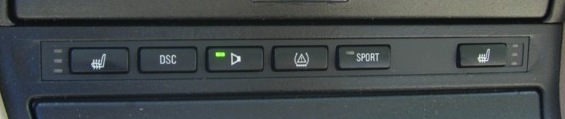
The button is located on the center console, in the same button panel as the heated seats, DSC and HK button that we already have. Your individual setup may vary based on the options of your car, so ideally, the replacement switch setup you locate will have all the other switches you currently have, in the same location, with the added TPMS button. Something to note, the panel you get will most likely be from an M3, so it'll also have the sport button, something that we cannot make use of, at least not without doing the Sprintbooster/sport button mod. But that's a whole other DIY! So, I digress, you'll need to get another button panel with the TPMS reset button. Example below (this is what mine looks like as well). The TPMS reset button is the one in the middle.
For the following part, the steps only reflect cars with OEM navigation as they will be different for cars without nav. For my car (with navigation) the steps are as follows. I didn't include many pics as none are really needed.
1. Remove shift knob and shift boot.
2. Remove the trim around the shift knob/boot, two philips screws. Don't forget to disconnect the two window switches.
3. Take a small flatblade screwdriver or thin pry tool (preferred) and pry the HVAC controls out of place from one side. The unit is only clipped into place, but it does have 4-5 connectors on the back. Gently pry it out so as not to damage it/the dash, and then disconnect all the connectors. There are no two alike, so no need to mark them.
4. Remove 4 philips screws that hold the lower trim piece in place. Two are hidden at the top, under where the HVAC controls were. Two are at the bottom, under where the shifter trim was. Remove all 4. Pull the trim out, but not too far.
5. There are two connectors on the back of the switch panel, disconnect them.
6. Remove two small Torx screws and remove the switch panel.
7. Install your new switch panel.
8. Complete part 3 now if possible, otherwise it'll be more work later to disassemble the center console for access to the switch panel connectors again for the wiring. Otherwise, reassemble the center console, knowing that your new switches won't do anything for the time being.
Part 3: The wiring
This is the part needed to actually make the reset button function. Its a lot of work for a mod that honestly won't get used much, but its still nice to have, and if you're going to do it, might as well do it all and do it well. That being said, basically, an additional wire is needed that runs from the reset button to the DSC module. The wire has to be ran from the large flat connector at the switch panel, through the dash, to the drivers side, through the firewall, and then up into the DSC module connector. Luckily, there is a ventilation port for the DME housing, so it makes for a very easy location to run the wire. Personally, I started at the DME and ran back to the switch panel. Before starting any work on the car, you'll need to make a jumper wire with the correct pins on either end. I received clipped connectors from someone parting a car. It was easiest as the connectors were already crimped on, all I needed to do was take one pin from each connector and then insert about 6' of wire in between to make the wire needed.
1. Pop the hood, and then remove the cabin air filter and housing. Once you remove the filter cover and filter, you'll see 4 Torx screws. Remove them and the whole housing will come out. Make sure to unclip the wire loom that runs across the front of the housing.
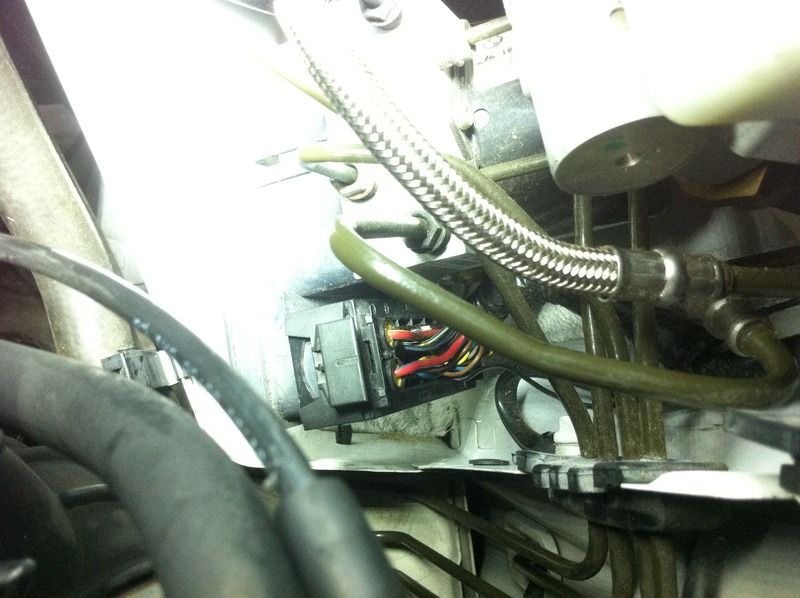
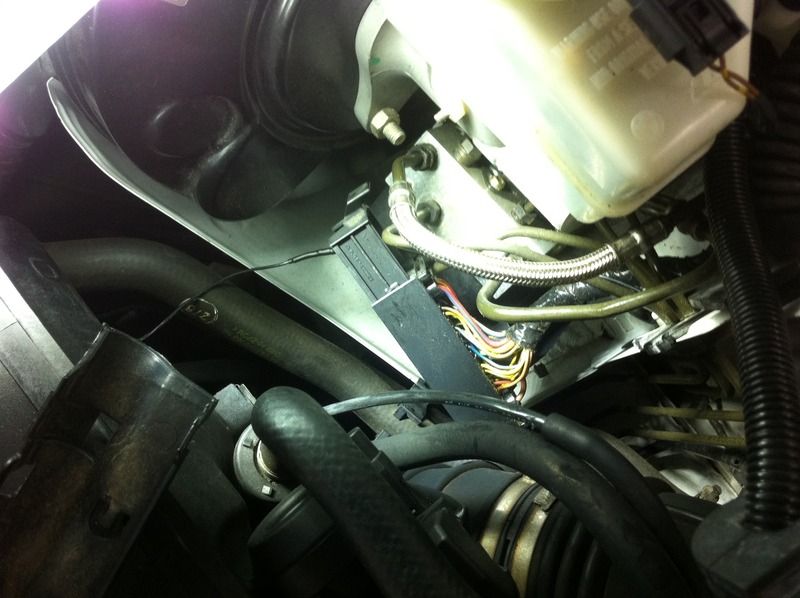
2. Remove the heat/splash shield on the drivers side that protects the DSC and brake master cylinder. This will help you access the DSC plug. Pic shows it in place below.
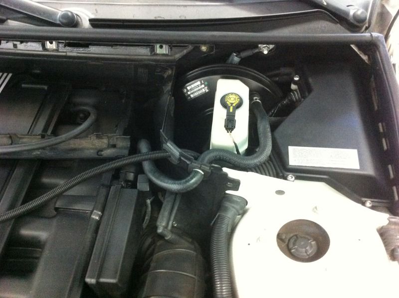
3. Disconnect the DSC plug from the unit. It is a large plug, down low on the front side of the DSC module, set at an angle. The tab on the upper end of the plug will need to be pulled to slide the plug off. Like many other plugs on the E46, it is a slide lock style connection. Pic below.
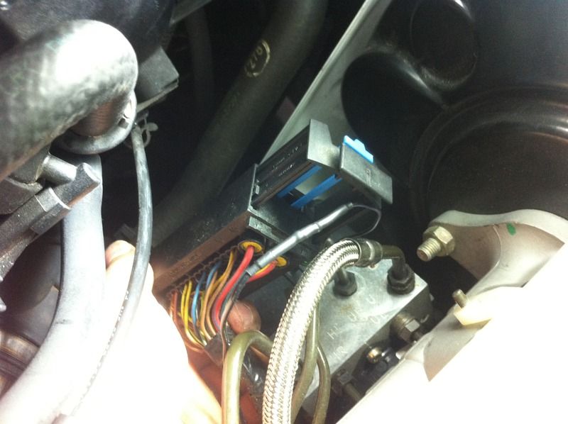
4. Once the plug is disconnected, pull it up a bit to gain better access. On the same end as the slide lock, you'll see a blue tab, you'll need to slide that out as well. This blue portion locks the pins into place on the connector. Sliding it out will open the port for the needed wire terminal to be inserted.
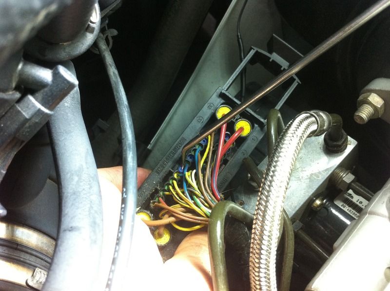
5. Locate pin #40. You'll see on the face of the connector that there are small numbers, depicting the pin numbers. If you count back from the end pin (numbered 46) you'll find that #40 should be empty. Ensuring the same hole, flip the connector over. You'll find an empty rubber grommet in the hole. Remove it.
Ok, so this is one end of where the wire needs to be installed. Like I said, I started here and ran it back up to the center console. To fish through the firewall, you'll need some sort of cable or a metal coat hanger. I used a steel cable. If you look under the dash, you'll find the hole to fish the wire through.
Last edited by JupiterBMW; 01-12-2016 at 08:16 PM.
2011 E90 Lemans Blue/Bamboo Beige M3- Harrop Supercharged IG: lmb_zcp
2013 F25 Alpine White/Chestnut X3 35i- Family Hauler
2006 R53 British Racing Green/Panther Black Mini Cooper S FOR SALE! DM for details!
Past: 2010 X5M, 2014 328d, 2003 330i ZHP, 2004 330i ZHP, 2012 X3 35i
WTB!! 2009-2012 E91 328i Touring Contact me with info!


 Reply With Quote